| Home | Current Systems | Former STK Products | EOL Systems | Components | General Info | Search | Feedback |
|
|
Oracle System Handbook - ISO 7.0 May 2018 Internal/Partner Edition | ||
|
|||
SPARC 5-2 LEDsThe SPARC 5-2 server provides the following LED groupings:
SPARC T5-2 Front Panel LEDs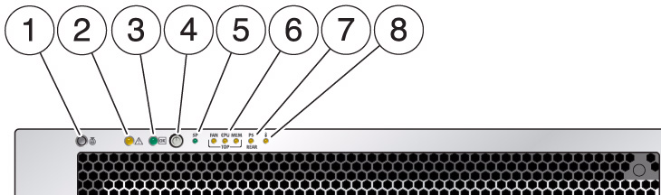
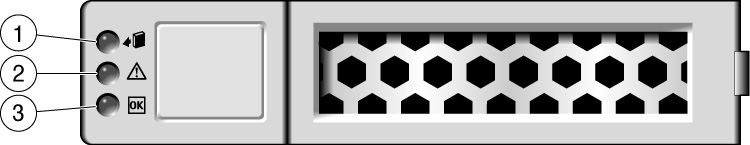
SPARC T5-2 Disk Drive LEDs
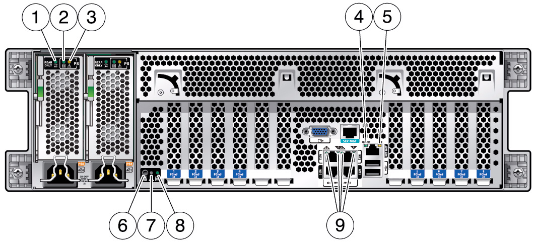
SPARC T5-2 Rear Panel LEDs | |||||||||||||||||||||||||||||||||||||||||||||||||||||||||||||||||||||||||||||||||||||||||||||||||||||||||||||||||||||||||||||||||||||||
| LED Name | Description |
|---|---|
| 1. Power Supply AC OK LED - (Off) | No AC power applied to this power supply | 1. Power Supply AC OK LED - Green Steady On | AC power is applied to this power supply and is within specifications. | 1. Power Supply AC OK LED - Amber Steady On | AC power is applied to this power supply and is below 85V. |
| 2. Power Supply DC OK Led | Off - 12V DC output from this power supply is disabled or not within spec. | 2. Power Supply DC OK Led (Green) | Steady On - 12V DC output from this power supply is present and within specifications. |
| 3. Power Supply Fault LED | Off - Steady state, no service action is required. |
| 3. Power Supply Fault LED (Amber) | Steady on - A fault has been detected on this power supply. |
| 4. NET MGT Port Link/Activity LED (green on left) | Steady On - A link is established. |
| 4. NET MGT Port Link/Activity LED (green on left) | Blinking - A link is established and there is activity on the port. |
| 4. NET MGT Port Link/Activity LED (green on left) | Off - No link is established. |
| 5. NET MGT Port Speed LED (Green and Amber on right) | Green Steady On - The link is operating as a 1-Gbps connection (fastest speed). |
| 5. NET MGT Port Speed LED (Green and Amber on right) | Amber Steady On - The link is operating as a 100-Mbps connection (medium speed). |
| 5. NET MGT Port Speed LED (Green and Amber on right) | Both LEDs Off - The link is operating as a 10-Mbps connection (slowest speed). |
| 6. Locator LED and button (White) | Turn on the Locator LED by pressing the Locator button. When lit, the LED blinks rapidly. |
| 7. Service Required LED (Amber) | The fmadm faulty command provides details about any faults that cause this indicator to light. Under some fault conditions, individual component fault LEDs are lit in addition to the Service Required LED. |
| 8. Power OK LED (Green) | Off - Server is not running in its normal state. System power might be off. The SP might be running. |
| 8. Power OK LED (Green) | Steady On - Server is powered on and is running in its normal operating state. No service actions are required. |
| 8. Power OK LED (Green) | Fast blink - Server is running in standby mode and can be quickly returned to full function. |
| 8. Power OK LED (Green) | Slow blink - A normal but transitory activity is taking place. Slow blinking might indicate that system diagnostics are running or that the system is booting. |
| 9. Host Ethernet Port Link/Activity LED (Green) These LEDs, from left to right, represent NET1, NET0, NET3, and NET2. |
Steady On - Server is not running in its normal state. System power might be off. The SP might be running. |
| 9. Host Ethernet Port Link/Activity LED (Green) | Blinking - A link is established and there is activity on the port. |
| 9. Host Ethernet Port Link/Activity LED (Green) | Off - No link is established. |
| LED Name | Description |
|---|---|
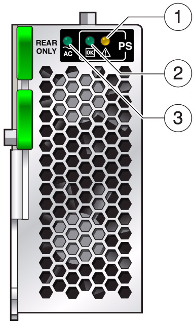
| 1. Service Action Required (Amber) | The power supply is faulty. Service action is required. |
| 2. OK (Green) | Both DC outputs (3.3V standby and 12V main) are active and within regulation. |
| 3. AC Present (Green) | AC voltage is applied to the power supply. |
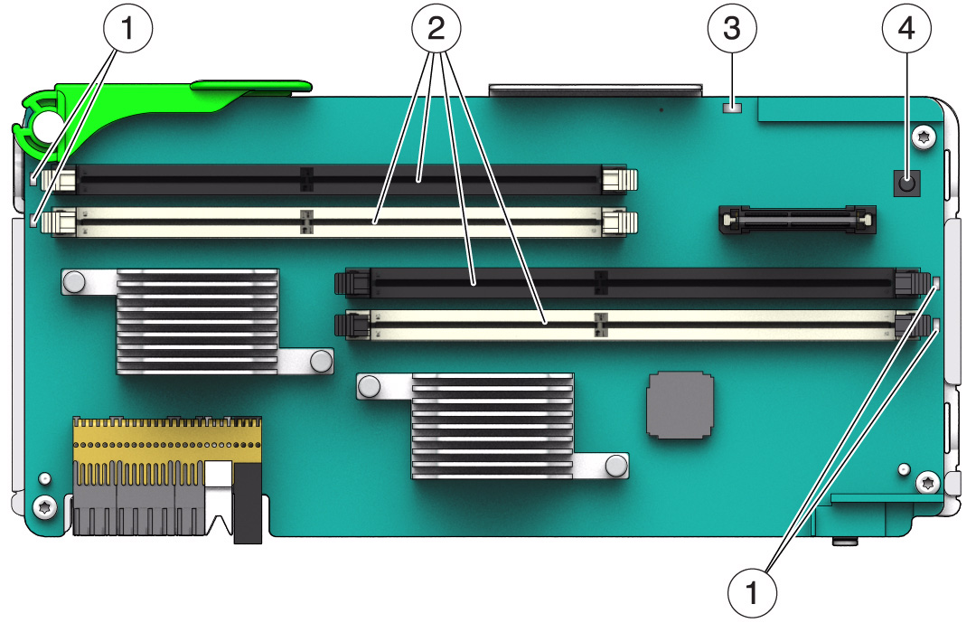
| LED Name | Description |
|---|---|
| 1. DIMM Fault LED (Amber) | Identifies each faulty or misconfigured DIMM when you press the memory riser remind button. |
| 2. DIMM slots | A notch toward the middle of each slot ensures that the DIMM is correctly oriented. |
| 3. Memory riser power LED (Green) | Indicates that the riser is operating normally. |
| 3. Memory riser power LED (Amber) | Indicates that the riser has a fault. |
| 4. Memory riser remind button (Blue) | Push this button to identify the faulty or misconfigured DIMMs. |
|
Copyright © 2018 Oracle and/or its affiliates. All rights reserved. Feedback | |||