Ultra 80
Jumper Settings
| JUMPER |
PINS |
SETTING |
DESCRIPTION |
| J0102 |
2-3 |
In |
Bypass CPU0 in scan chain |
| J0202 |
2-3 |
In |
Bypass CPU1 in scan chain |
| J0302 |
2-3 |
In |
Bypass CPU2 in scan chain |
| J0402 |
2-3 |
In |
Bypass CPU3 in scan chain |
| J2804 |
1-2
2-3 |
In
In |
RS-232 +12Vdc
RS-423 (default) |
| J2805 |
1-2
2-3 |
In
In |
RS-232 -12Vdc
RS-423 (default) |
| J3001 |
1-2
2-3 |
In
In |
FPROM write protected (default)
FPROM write enabled |
| J3002 |
1-2
2-3 |
In
In |
Select Flash PROM (default)
Select ROMBO |
| J3102 |
1-2
2-3 |
In
In |
FPROM high half booting
FPROM low half booting (default) |
| J3201 |
1-2
2-3 |
In
In |
÷3 mode (360MHz)
÷4 mode (400MHz/450MHz) |
| J3202 |
2-3 |
In |
(on -07/08 FAB, removed from -09) |
| J3705 |
1-2
2-3 |
In
In |
QAM WGS- to SPEAKER OUT- (default)
QAM WGS- to POWERON_L |
| J3706 |
1-2
2-3 |
In
In |
QAM WGS+ to SPEAKER OUT+ (default)
QAM WGS+ to SUPPLYTRIP_L |
|
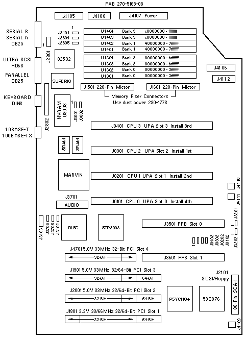
Module Slot Numbering
| SOCKET |
INSTALL |
UPA |
OBP/OS |
| J0401 |
3rd |
UPA 3 |
CPU 3 |
| J0301 |
1st |
UPA 2 |
CPU 2 |
| J0201 |
2nd |
UPA 1 |
CPU 1 |
| J0101 |
4th |
UPA 0 |
CPU 0 |
PCI Slot Numbering
| SLOT |
BUS |
DEVICE TREE |
| 4 |
B |
pci@1f,4000/*@5,* |
| 3 |
B |
pci@1f,4000/*@2,* |
| 2 |
B |
pci@1f,4000/*@4,* |
| 1 |
A |
pci@1f,2000/*@1,* |
PCI Bus B shares the address/data bus with on-board Audio, Ethernet, Flash,
Floppy, Keyboard, Mouse, NVRAM, Parallel, SCSI, and Serial devices.
Miscellaneous Connectors
| CONNECTOR |
PINS |
DESCRIPTION |
| J2801 |
1-8 |
Serial test (factory use) |
| J2802 |
1-32 |
ROMBO (factory use) |
| J3101 |
1-2
2-3 |
Button XIR (factory use)
Button POR (factory use) |
| J3103 |
1-8 |
JSCC (factory use) |
| J4105 |
1-18 |
DC-DC Converter |
| J4106 |
1-14 |
Power Supply sense |
| J4107 |
1-28 |
Power Supply +3.3V and +5V |
| J4108 |
1-10 |
DC-DC converter |
| J4109 |
1-2 |
Fan power |
| J4110 |
1-2 |
Fan power |
| J4111 |
1-8 |
Interlock, LED, speaker, and power switch |
| J4112 |
1-10 |
DC power to internal peripherals |
System Codenames
| System |
Codename |
| Ultra 80 |
Quasar |
| Enterprise 420R |
Quahog |
| Netra t 1400/1405 |
Lightweight 3 |
Notes
- The minimum OS is 2.5.1 HW: 11/97, 2.6 HW: 5/98, or 7 HW: 8/99.
- The flash PROM is soldered to the system board.
- Use the Flash PROM Programming Utility to update the flash PROM.
- 64-Bit PCI boards do not fit into Slot 4. Connector J3601 interferes with
the 64-Bit PCI extension connector.
- DC-DC Converter 300-1407 connects to J4105 and J4108 on the
system board.
SCSI Bus Notes
- The internal SCSI bus is controlled by /pci@1f,4000/scsi@3.
- The external SCSI bus is controlled by /pci@1f,4000/scsi@3,1.
Memory Notes
- DIMMs are required on both the Riser Board and the System Board.
- Every populated bank must contain four same-size DIMMs. Four
same-size DIMMs are a "quad".
- To activate 2-way interleaving, quads must be installed in
banks 0 and 1, which are non-adjacent banks.
(A third quad may be installed in either remaining bank, but that
will disable interleaving.)
- To activate 4-way interleaving, all four banks must be populated
with quads.
- Each bank addresses 1GB of memory.
- Damage to the Mictor Connectors can occur if DIMMs are installed
or removed when the Riser Board is installed on the System Board.
References
 Ultra 80 Workstation Documentation. Ultra 80 Workstation Documentation.
- Sun Enterprise 420R Server Documentation.
Rear View
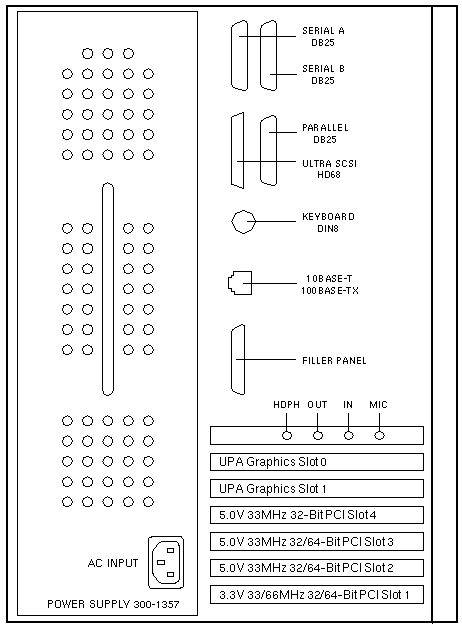
|